If you ask any person inexperienced in electrical engineering what is in the electrical panel, then an immediate answer will follow - automatic machines. Although there may be, in addition to circuit breakers (this is the correct name for automatic machines), there may be differential circuit breakers, load switches, contactors, impulse relays, and much more. The purpose of this article is to learn how to select circuit breakers from the whole variety of modular devices, what they are intended for, how to choose them correctly, how to connect the machine in the shield and what to do when triggered.
At first glance, it may seem that an ordinary person who is absolutely unfamiliar with engineering in general and electrical engineering in particular does not need to know anything about circuit breakers, because professionals did the wiring in an apartment or house. It is possible that this is so, but what will a person do if the voltage suddenly disappears in the entire apartment or house or in some part of them. Of course, a person will open the shield, look at which “knocked out”, and again move the lever to the “on” position.
It is in this action that the main mistake of “ordinary people” lies, because before turning on a triggered modular device, you need to figure out the reason for its triggering. Therefore, do not be surprised when, after switching on again, immediately or after a while, a second switch-off follows. Without eliminating the cause, you should never re-enable modular devices, including circuit breakers (hereinafter machines). This can lead to sad consequences both for the health and life of a person, and for property.

The fact is that different protection devices have their own functions, therefore the reasons for the operation of automatic machines and (RCD) are completely different. And in most cases, this does not apply to the quality of the installation of electrical wiring. Of course, an experienced electrician will always find the cause. But if incidents with electricity occur at night or on a weekend, then not every electrician will agree to quickly solve the problem that has arisen, and if he does, then the owners will have to pay well out of their own pocket for the urgency.
As the electricians themselves say, 50% of cases of protection devices tripping are commonplace and occur through the fault of the owners themselves and the wiring has nothing to do with it. That is why elementary basic knowledge about protection devices, their purpose and the rules for responding when they are triggered will be very useful. The authors of the article will try to explain everything in an understandable language, without going into the wilds of technical nuances that will be of interest only to specialists, but not to “ordinary people”.
What is a circuit breaker and what is it for?
A circuit breaker (automatic) is a device that is designed to switch (in other words, turn on and off) an electrical circuit. That is, here we mean that you can manually turn on and off the electrical circuit with the help of a lever.

However, the name itself - a circuit breaker, suggests that the machine should automatically turn off the load. In what cases does this happen?
- When the circuit protected by the circuit breaker flows a current that exceeds the allowable. And the greater the excess current, the faster the shutdown occurs.
- When very large currents occur in the protected circuit, which are unusual for the load - the so-called short-circuit currents. In these cases, the machine reacts very quickly - within fractions of a second.
An overload can occur when one powerful load is simultaneously switched on in one circuit protected by the machine, for which neither the circuit breaker nor several powerful loads are designed. For example, in one socket circuit of six sockets, an electric kettle, an iron, an electric fireplace, a microwave oven, a double boiler and a hair dryer are turned on at the same time. Naturally, with such a load, the current will exceed its nominal values \u200b\u200bmuch, this will heat up the wires very much, which can lead to melting of the insulation and further to a short circuit. The machine must not allow this and must cut off the circuit before the wires get very hot.

Short-circuit currents can occur when a breakdown of the insulation to the case occurs in any device or the phase and neutral conductors are closed. According to Ohm's law, the lower the resistance, the greater the current. The greater the current, the more heat is generated, which leads to melting and ignition of the insulation. Short circuits are the most common cause of electrical fires. That is why a very important function is assigned to the machine - to instantly respond to short-circuit currents, that is, to such currents that are many times higher than the nominal ones. The reaction time of the machine must be such that the wires do not have time to heat up to dangerous temperatures.
From all of the above, one important conclusion follows: the circuit breaker is designed to protect wires, cables and various electrical devices included in the circuit from overload and short circuit. There is no mention of a person. Therefore, the main thing should be understood - the machine does not save a person from electric shock. The machine saves cables and wires.
Let's take an example. Let's say the lighting circuit in the apartment is protected by a 10 Amp machine and a person, changing a light bulb in a lamp, accidentally touched a live phase conductor, and touched the grounded refrigerator case with another part of the body. An electric current begins to flow through the human body, which depends on the resistance - the larger it is, the less current. In calculations, the resistance of the human body is taken to be 1 kOhm, which means that the current will be I=U/R=220/1000=0.22A=220mA. For a fatal electric shock, 80-100 mA is enough for a person, and the machine has a rated current thousands of times greater. Therefore, we repeat - the machine does not save a person from the damaging factors of electric current. Of course, a triggered machine can save someone's life if it prevents the electrical wiring from igniting, but it does not save a person from direct exposure to electric current.
Briefly about the "inner world" of the machine
A circuit breaker is a complex electromechanical device. Some modern models of machines are equipped with electronic units that more accurately monitor the flowing currents, but in the article we will consider the “classic” device. The cutaway machine is shown in the following figure.

Terminals are located at the top and bottom of the machine, and it is always assumed that the input is located at the top and the output is at the bottom. The upper terminal is rigidly connected to a fixed contact, and the lower terminal is connected to a thermal release, which is a bimetallic plate that bends when heated. The end of the bimetallic plate is connected by a flexible conductor to one of the terminals of the electromagnetic release solenoid. The other output of the solenoid is connected by a flexible conductor to a moving contact.
The release mechanism is designed in such a way that the movable contact is spring-loaded and securely fixed both in the on and off state. In addition, the springs allow switching very quickly, which avoids severe burning of the contacts during a spark or arc discharge, which can occur precisely at the moments of disconnection.
The release mechanism can be actuated in three ways:
- Turning on the machine, that is, when the movable contact is pressed against the stationary one, is possible only manually, through the control lever of the release mechanism. You can also turn off the machine manually.
- During overloads in the circuit, a current that exceeds the rated current passes through the bimetallic plate of the thermal release and heats it up. Under the influence of temperature, the plate bends and presses the lever of the release mechanism, which turns off the machine. The higher the current overload, the faster the plate heats up and the faster the mechanism operates.
- If short-circuit currents occur in the circuit, then the current passing through the solenoid of the electromagnetic release induces a magnetic flux capable of drawing in the spring-loaded core of the solenoid, which, in turn, acts on the moving contact and opens the circuit. The reaction time in this case can be thousandths of a second for good automata.
At the moment of disconnection, a spark discharge may occur between the moving contact, which ionizes the atoms of the gases that make up the air. Ionized gas is a good conductor, so an electric arc can break out, the temperature in which can reach several thousand degrees. Naturally, such a thermal effect will burn out the circuit breaker very quickly if special measures are not taken.

The machines always have a special arc chute, which is a set of copper or steel plates coated with copper, which are isolated from each other. When the arc lights up, it forms a powerful magnetic field, which induces an EMF in the plates, which also forms its own magnetic field opposite in polarity. These fields interact with each other, the arc is drawn into the plates of the arc chute. The plates “shred” the arc into pieces and cool it down, causing it to die out quickly. When the arc burns, a large amount of gases are formed, which freely exit the machine body through a special hole located below the arc chute. This process may take a fraction of a second, but even this time is enough for a spark discharge or arc to "scorch" the contacts a little.

Over time, with frequent switching on and off of the machines, the contacts burn out. There were times when the contact pads of circuit breakers were made of electrical silver, there are such devices now, but they are not used in household electrical wiring. Therefore, it is not necessary to “click” with the lever of the machine without special need, since with each action there, at least a spark discharge jumps, causing erosion of the contacts. The machines are mainly designed to protect the cable or wire, and for switching there are special devices - load switches, called in Russian knife switches.
Find out its purpose, basic schemes, common mistakes in a special article on our portal.
How to choose the right circuit breaker
Before installing the circuit breaker in the electrical panel, it must be properly selected so that it matches both the cable and the nature of the load. Therefore, we will consider the main characteristics of modular machines, which are always indicated on their markings. For a specialist, marking says a lot, but for an “ordinary person” it says nothing. Therefore, you need to learn how to read it, especially since there is nothing complicated about it.
Educational program for marking machines, selection of the desired model
The figure shows a typical marking for all circuit breakers. We will consider all the points in sequence and, along the way, we will comment on which particular machines are needed for various purposes.

Trademark
At the top of the front panel of the machine, the trademark is always indicated, which in other words means the manufacturer. For protection devices, this is of great importance, since it is better to choose a machine from a well-known brand. These are: ABB, Legrand, Hager, Merlin Gerin, Schneider Electric, IEK, EKF. On the issue of choosing a specific model and series, it is better to consult a good (not ZhEKovsky) electrician.
Rated voltage and frequency
If the machine has the inscription 220/400V 50 Hz, this means that this machine can operate both in single-phase and three-phase AC circuits with a frequency of 50 Hz. Most of the machines used in household wiring have this capability.
Rated current
This is one of the main characteristics, which indicates what maximum current in amperes can flow through the machine for a long time without it tripping. It is designated I n. If the current becomes more than the nominal by 13%, i.e. I=I n *1.13, then the thermal release starts to work, but its operation time will be more than an hour. Upon reaching I=1.45*I n the trip time of the thermal release will already be less than an hour and the greater the current, the shorter the trip time.
The rated current of the machine must always correspond to the cross section of the cable or wire of the circuit it protects, but not to the load power. The machine should not allow them to overheat when an electric current flows, but in real life the opposite often happens.
For example, a family has acquired a washing machine, and when it is connected to an existing outlet, after a while the machine knocks out in the access panel, since the total load is higher than it can allow. An electrician who came from the housing office offers a "brilliant" solution to change the machine to another one with a higher rated current. For example, there was a 10 A machine in the shield and it is proposed to change it to 16 A, or even to 25 A, so that it would be “more reliable”. The machine is changing and, to the delight of the owners, it really stopped knocking out when the washing machine was running. And it is made with aluminum wire with a cross section of 1.5 mm 2, which is far from uncommon in houses built in the era of the USSR.
Naturally, at peak loads, the wire will overheat, its insulation will melt, but the machine will not react in any way, since its response threshold is much higher. Unfortunately, such situations are far from uncommon. And the owners will be very lucky if there is no fire, but a short circuit occurs, which will make the machine work.
You should understand the simple rules that will help you choose the right machine that is guaranteed to protect the wiring from overheating.
- or wires must match the load.
- The rating of the circuit breaker should only correspond to the cross section of the cable or wire, but not to the load.
The table below shows the correspondence between the section of the copper cable or wire and the rated currents of the circuit breakers. In any case, it is necessary to be guided by precisely this correspondence and nothing else. No exceptions and arguments like "I've done this a hundred times."

It can be seen from the table that the machine does not allow using all the possibilities of a cable or wire for passing electric current, but limits them. And this is done on purpose, the circuit breaker is a kind of “weak link”, which will not allow the cable or wire to be “stressed” much, which, from a safety point of view, is very useful.
Circuit breakers for rated current are 1A, 2A, 3A, 6A, 10A, 16A, 20A, 25A, 32A, 40A, 50A, 63A.
Time-current characteristic
Before the value of the rated current in the marking of the machine, there is an alphabetic index, which reflects the time-current characteristic (VTX). It is not known for what reason, but this is given, from the point of view of the authors, not enough attention. Let's figure out what this feature is.

The figure shows a graph of the dependence of the response time of the machine on the multiplicity of the flowing current to the nominal, that is k=I/I n. The graph is divided into three colored zones: green, blue and yellow, which corresponds to the time current characteristics B, C and D. The following conclusions can be drawn from the graph:
- If k is greater than 3 but less than 5, the automaton belongs to category B.
- If k is greater than 5 but less than 10, the automaton belongs to category C.
- If k is greater than 10 but less than 20, the automaton belongs to category D.
What does this mean in human terms? It can be seen from the graph that in any categories of automata, the greater the multiplicity of the flowing current in relation to the rated current, the faster the operation will occur. Circuit breakers with BTX category B are the fastest to respond to overcurrent, followed by category C circuit breakers, followed by D. There are also circuit breakers with K and Z characteristics, but they are not used in apartment buildings either.
It should be noted that the graph is given for certain external conditions, namely an ambient temperature of +30°C. When the temperature rises, the automata will operate at slightly lower currents, and when lowered, on the contrary, at large ones. This difference is not so significant, but it is still there. A very great influence on the operation of circuit breakers is exerted by their "neighbors" on the electrical panel, which, heating up when an electric current flows through them, heat both the air inside the shield and the nearby equipment. That is why experienced electricians try to choose models of electrical panels that have a lot of free space inside and, when assembling them, do not try to fill them with modular equipment “to the eyeballs”.
The question is, why divide the circuit breakers into categories according to VTX. After all, you can simply make such an apparatus that will simply react by turning off when the current flowing exceeds the nominal one. But not everything is so simple. Some types of electrical loads, when turned on, consume currents that are much higher than during operation. For example, the electric motors of a vacuum cleaner or a refrigerator compressor can consume current that is 3-8 times the rated current at the time of startup. If the machines react every time to such an excess, then life will turn into a living hell - every time the refrigerator is turned on, the machine in the shield vibrates. That is why the machines use thermal releases, which have a certain inertia, which allows you to allow a short-term excess of current that does not lead to overheating of the wires. In any case, the thermal release is configured so that it turns off the circuit before the cables and wires enter a dangerous mode for them.

In the electrical wiring of apartments and private houses, circuit breakers from category B and C are used. When choosing a specific model, the nature of the load should be taken into account. For active loads, that is, those that do not consume increased currents at start-up, you should choose machines with BTX type B. This applies to lighting and socket circuits. Reactive loads will already require type C BTX machines. These include refrigerators, air conditioners, washing machines and dishwashers, home workshops where power tools are used.

Unfortunately, it is very difficult to find type B circuit breakers in electrical goods stores. This is due to the low demand for them. The lion's share of the machines sold are VTX type C. But the authors of the article strongly recommend not to spare money and use machines of type B for active loads. Even if you have to order them and wait for a while. The fact is that by combining automatic machines with characteristics B and C, it is possible to achieve selectivity in the operation of protection devices.
Let's take an example. Suppose an incandescent lamp burned out in one of the lamps, but at the same time the spiral closed. Surely everyone has come across such a situation when, when the light is turned on, the lamp flashes and immediately goes out with a characteristic click and at the same time knocks out the machine. It’s good if the machine worked, which only protects the lighting circuit of the room, but it can happen that the machine located in the driveway is knocked out. Moreover, it happens that in the apartment panel the machines did not react, but the entrance door did. If this happens, then selectivity is poorly organized in the organization of electrical wiring.
The main principle of selectivity is that the protection devices closest to the source of the problem should operate first. If for some reason they did not work, then other devices higher in the hierarchy should respond. In the case described with a lamp, it is possible to put an automatic machine with type B VTX on the lighting circuit, and install a category C automatic machine in the entrance shield. Then, when the lamp coil is closed, the more “nimble” type B automatic machine will work first of all, while the access machine “dulls”. In this case, its slower response is beneficial, as it will not cause the entire apartment to shut down.
Rated breaking capacity
This characteristic can also be called the limiting switching capacity (PKS). PKS shows at what maximum short circuit current the machine will still be able to open the circuit at least one (and this will most likely be the last) time. Standard PKS values are 4.5 kA, 6 kA, 10 kA. For domestic use, 4.5 kA is quite enough, but if the substation is nearby, then it makes sense to use automatic machines with 6kA PKS. Automatic machines with PKS 10 kA are used only in industry.
Current limiting class
This characteristic has three values - 1.2 and 3, and if there is no this marking, then the machine belongs to class 1. It shows how quickly the machine will react to the appearance of short-circuit currents. If the thermal release can “tactfully wait” when an overload occurs, then the electromagnetic one should act “decisively and boldly” when a short circuit occurs. The current limiting class precisely reflects the degree of “decisiveness” of the machine and its reaction time.

Class 1 opens the circuit in one half-cycle, which is approximately 10 ms in time, class 2 - in ½ half-cycle (5-6 ms), and class 3 in 1/3 half-cycle (3 ms). Naturally, the higher the class, the better, but also more expensive.
Number of poles
Modern apartment or house switchboards use modular circuit breakers with 1, 2, 3 or 4 poles. Single-pole and two-pole circuit breakers are designed to protect single-phase circuits, and three- and four-pole circuit breakers are designed for three-phase circuits. According to the number of poles, circuit breakers occupy the number of places (modules) in the electrical panel. One place is 17.5 mm.
Video: How to choose circuit breakers
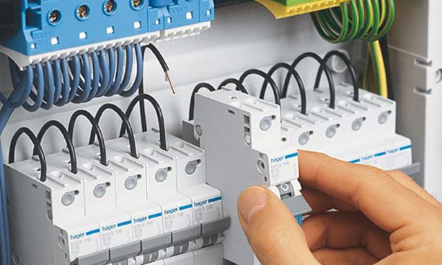
As noted above, modern circuit breakers used in household wiring are modular equipment, which, along with other control, switching, accounting and protection devices, have housings of standard sizes in length and height, and the width is always a multiple of one module (place) equal to 17 .5 mm.
All modular equipment in electrical panels is mounted on a DIN rail, 35 mm wide, with a latch. To install, simply snap the machine onto the rail, and then, moving it to the left or right, set it to the desired position. And to remove it, you will already need a screwdriver with a straight slot, which you need to pry and pull up the spring latch.

To install and connect the circuit breaker to the electrical panel, you will need a standard set of electrical tools:
- A set of screwdrivers, both slotted and cross-headed. You should pay attention to which screws, with which slot, are used in the terminals of the machine. There are two options: a Philips cruciform (numbered 2 in the figure) or a Pozidriv cruciform (numbered 3 in the figure). They are designated PH or PZ, respectively.

Each slot has its own tool: a screwdriver or a bit
- Pliers of various sizes.
- Wire cutters or cable cutter.
- Stripping tool - stripper.

- If stranded wires are used to connect, then you will need a tool for crimping the lugs - a crimper.

- indicator screwdriver.
Let's describe the process of mounting and connecting the circuit breaker in the electrical panel.
| Image | Description of process steps |
|---|---|
 | The electrical panel is completely de-energized, measures are taken to prevent unauthorized switching on of voltage. An indicator screwdriver checks the absence of voltage in the shield. |
 | The machine of the selected denomination snaps into place on the DIN rail. |
 | If there are empty spaces to the left and right of the machine, then it is advisable to use special stops that prevent the equipment from moving left and right along the DIN rail. |
 | When connecting a single-pole machine, the phase from the input device or RCD (individual or group) must be supplied to the upper terminal, and the phase of the protected circuit must be removed from the lower terminal. |
 | When connecting a two-pole machine, a phase must be applied to the upper left terminal, and to the right zero. The phase of the protected circuit should “leave” from the lower left, and zero from the right. |
 | When connecting a three-pole machine, the phases must be supplied to the upper terminals in the order they appear from left to right A, B, C (L1, L2, L3). From the lower terminals, respectively, the phases of the protected circuit should “leave” in the same order. |
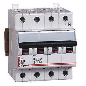 | A four-pole machine is connected similarly to a three-pole machine, only a neutral wire is added - the far right. |
 | In the electrical panel, suitable wires and wires of the protected electrical circuits are laid to the corresponding terminals of the circuit breakers. Incoming are laid to the upper terminals, and outgoing to the lower. The only way! When laying, existing bundles of wires should be used. If necessary, the wires to be laid are tied to the bundles with plastic clamps. |
 | When laying wires, sharp turns should be avoided, which can provoke creases. Also, do not pull the wire with tension. |
 | When the wires are laid to the terminals of the machines corresponding to them, their required length is measured so that the wire freely enters the terminal. Excess ends are cut off. |
 | The stripper removes the insulation from the ends of the wires by 10 mm. In the absence of a stripper, this can be done with a construction knife, but at the same time, one should try not to cut the insulation perpendicular to the wire - this can provoke a further crease of the wire. |
 | If stranded wires are used, then they must be terminated with NShVI-type lugs, which are crimped with a special tool - a crimper. |
 | If the circuit breaker is located next to others in the electrical panel and one phase or a phase together with zero is “distributed” to them all, then it is advisable to use special comb tires, which, like automatic machines, are one, two and three-pole. |
 | In the absence of combs, jumpers can be made from the mounting wire PV3 and lugs NShVI (2), designed to crimp two wires. It is impossible to place two separate wires under the terminal of the machine. |
 | After checking the compliance of the installation with the circuit diagram of the electrical panel, the wires are placed in the previously released terminals of the machine and clamped with a screwdriver with a force of 0.8 N * m. Do not try to tighten "with all the dope", as this can lead to breakage of the body of the machine. |
 | Voltage is applied to the electrical panel, all protection devices are turned on, the presence of voltage at the input and output of the machine is checked with an indicator screwdriver or a multimeter. |
 | The insides of the electrical panel are closed with a protective cover - a plastron. A marking is placed on the circuit breaker indicating that it belongs to the protected circuit. Marking is also done on the plastron. |
Video: Circuit breakers - polarity and wiring diagrams
What to do if the machine in the electrical panel has tripped?
If during the operation of the electrical wiring the circuit breaker tripped, then there could be many reasons for this. Therefore, do not rush to immediately turn it back on, but you should try to find out the source of the problem. In doing so, you should be guided by the following:
- Any disconnection of the machine causes a strong heating of its insides, especially the bimetallic plate of the thermal release and the solenoid. Before turning on the load, it is necessary to allow a few minutes of exposure to cool down.
- While the machine is cooling down, you need to walk around the apartment or house and inspect all sockets, switches, lamps, powerful consumers of electricity. The smell of burnt insulation, darkening from exposure to fire, hot plugs can tell you a lot and point to the source of the problem.
- If everything is in order with the selectivity in the electrical panel and only one machine protecting a particular circuit has worked, then the task is simplified, since it is necessary to inspect the consumers of only this circuit. It is much worse when the automatic input worked, and others "ignored" the problem. Then you will have to turn off all the lines protected by circuit breakers, turn on the input machine and turn on all the circuits in sequence, one at a time. After turning on any circuit, it is necessary to give a certain exposure time and at the same time inspect all electrical appliances that are connected to the machine.
- If, when the automata are turned on sequentially, one of them triggers or turns off the input automaton, then the source of the problem has already been localized and the problem must be sought in a specific circuit. This may be some kind of faulty consumer of electrical energy, a burned-out lamp with a closed filament, melted insulation in some section of the wiring, and much more. To find out what the matter is, when the machine is turned off, turn off all consumers of electricity in this circuit, and then turn on the machine. If it works, then the problem is in and you can’t do without the help of specialists. If not, then all consumers must be connected in series, which will help identify a faulty device.
- Turning off the machine in some separate line or introductory can provoke a very large load. For example, the washing machine, dishwasher, air conditioner and electric oven are turned on at the same time. The input machine may not be designed for such a load, and therefore turns off the circuit. In this case, it is necessary to divide the operation of powerful electrical appliances by time.
- Hot summer weather combined with high loads can also cause protection devices to trip.
- And the last reason is the malfunction of the circuit breaker itself. It is possible that before that it had repeatedly triggered from increased currents, briefly endured short-circuit currents, and repeatedly extinguished the arc. All these influences, unfortunately, do not affect the life of the machine for the better. With the plastron removed, you can inspect the inside of the shield. A faulty machine can be identified by a melted body, burnt terminals, and other signs. Simply replacing the circuit breaker may solve the problem.

Video: Circuit breaker - why does it work in the heat?
Video: Circuit breaker knocks out
Conclusion
- The circuit breaker is designed to protect the cable or wire, not people.
- The rated current of the machine must strictly correspond to the cross section of the protected cable or wire.
- In circuits with a resistive load, it is better to use automata with a time-current characteristic of category B, and with a reactive load that has high starting currents - category C.
- A competent combination of circuit breakers with BTX B and C will ensure selectivity.
- When any circuit breaker trips, you must first identify the source of the problem. If you cannot do it yourself, then you should call a specialist.
Reliable and safe electrical wiring for you!
The most common means of protecting the line and electrical appliances are circuit breakers. When installing them, you must follow the basic rules.
- Input at the top of the machine, output at the bottom.
- The enable flag should be directed upwards when the machine is turned on.
- There should be no exposed wires.
How to connect a differential machine
The differential machine combines protection of the line from overloads and short circuits, as well as automatic switches, and protection of a person from electric shock as an RCD.
The case version does not differ from automata or RCDs, which makes it possible to install a differential automaton in standard boxes using a DIN rail.
Connecting a differential machine also resembles connecting a circuit breaker, with a small exception - two rules must be observed.
- It is necessary to observe the phasing of the connected wires. On the case of the differential machine, the designations of the zero and phase input are applied, which must be taken into account during installation.
- The neutral wire connected at the output of the differential machine is used only with the line that the device protects.
Differential automata are very reliable and unpretentious, but deviation from these rules does not guarantee the correct operation of the device.
For a single-phase network, the use of two-pole machines is preferable to single-pole ones. The reason is simple - when voltage appears on the neutral wire, with one movement of the flag, the circuit is completely broken, saving both the line and the electrical appliances connected to it. The housing version of the two-pole switch allows mounting on a standard DIN rail.
In this case, it should be borne in mind that the width of such an automaton is larger, as a rule, twice as much as a single-pole automaton. The upper contact pair is designed to connect the phase and neutral wires.

There are no strict rules for the location of the phase and neutral wires, but in the case of connecting a number of two-pole machines, it is necessary to follow the same tactics.
Having chosen, for example, the left contact for the phase wire, all other machines must be connected as well. The left contact is phase, the right contact is zero.
The stripped wires are fixed in the contacts using screw clamps. In this case, there should be no bare sections of the wire. Do not forget that there is a very small distance from the phase to the neutral wire and there is a possibility of a short circuit in the absence of insulation.
The most commonly used single-pole circuit breakers are reliable, easy to install and provide the necessary line protection against overloads and short circuits.

When connecting the circuit breaker, it is important that the body of the machine is securely fastened and, when turned on - turned off, does not fall off the attachment point.
To do this, use a mounting DIN rail or special boxes with pre-installed rails in the housing. The machine is mounted on a rail using a spring-loaded latch at the bottom of the case.
After installing the machine, a wire is connected to it. The top terminal of the machine is responsible for the input voltage, and the lower terminal is for the output. The wires laid and fixed on the wall are brought to the machine and cleaned.
In this case, be sure to observe the condition of the integrity of the insulation everywhere, except for the terminal blocks. The length of the stripped ends is quite enough at 1-1.5 cm.
The phase incoming and outgoing wire is clamped in the terminals of the machine, while the zero one can pass through the box or, if necessary, is fixed on the neutral rail.
Incoming and outgoing wires must be laid in such a way as to avoid excess length. The wires are laid parallel to each other and, if possible, all bends are made at right angles.
After installing the machine and checking all connections, the first switch-on must be carried out without a connected load on the line.
Greetings, dear readers of the site.
In continuation of a series of publications on circuit breakers, the next article in the cycle - circuit breaker connection diagram.
Let me remind you that a series of articles is included in the course.
We have already studied in detail the design and main technical characteristics of the machines, let's look at their connection diagrams.
Depending on the number of switched poles (or otherwise modules), the machines are divided into one-, two-, three-, four-pole (three phases and zero). In the event of an emergency, all poles of the circuit breaker are switched off at the same time.
One pole is a part of the machine, which includes two screw terminals for connecting wires (on the supply side and on the load side). The width of a single-pole circuit breaker mounted on a DIN rail is standard - 17.5 mm, multi-pole circuit breakers are a multiple of this width.
One- and two-pole are used in a single-phase electrical network. Most often, single-pole automata are used, they are installed in the break of the phase wire and, in the event of an emergency, disconnect the supply phase from the load.
Bipolar automata allow you to simultaneously turn off both zero and phase. They are most often used as introductory machines, or if it is necessary to completely disconnect the consumer from the electrical network, for example, a boiler, a shower cabin. They disconnect zero and phase from the protected section of the circuit and allow repair, maintenance or replacement of circuit breakers.
You cannot install two single-pole circuit breakers separately to protect the phase and neutral wires. For these purposes, bipolar automata are used, which turn off zero and phase at the same time.
Three- and four-pole are used in a three-phase electrical network. Three-pole circuit breakers are installed in a phase break (L1,L2,L3) of a three-phase network and are used to connect a three-phase load to it (electric motors, three-phase electric stoves, etc.). In the event of an emergency, they disconnect simultaneously all three phases from the load.
Four-pole machines allow you to simultaneously turn off both zero and all three phases, and are used as introductory machines in a three-phase electrical network.
Allows you to turn off all the electrical wiring of the apartment and disconnect the supply line from the group electrical circuits of the apartment.
Depending on the grounding system, the following input machines are used:
The introductory machine for the TN-S system (where the zero working N and zero protective PE conductors are separated) must be:
- single-pole with zero or two-pole;
- three-pole with neutral or four-pole.
The TN-S system is used in modern homes.
This is necessary to simultaneously disconnect the apartment's power supply from the zero working and phase conductors from the side of the power supply input, since the neutral and protective conductors are separated throughout.
For the TN-C system (where the zero working and zero protective conductors are combined into one PEN conductor), the introductory circuit breaker is installed single-pole (with 220 V power supply) or three-pole (with 380 V power supply). They are installed in the gap of the phase working conductors.
The TN-C system is used in Soviet-built houses (the so-called "two-wire").
According to the rules for the installation of electrical installations (clause 1.7.145), it is not allowed to turn on switching devices in the circuits of PE- and PEN-conductors, with the exception of cases of power supply to electrical receivers using plug connectors.
This requirement of the PUE is due to the fact that a situation is possible when two-pole circuit breakers cannot simultaneously turn off the phase and PEN conductors. And by disconnecting the PEN conductor, we thereby initiate its breakage.
When switched on under load, sticking or phase contacts may occur inside the machine (for example, a grain of sand may get on the contact group of the machine), in this case, when the machine is disconnected from the mains, the PEN conductor will break and a dangerous potential will be carried out to zeroed electrical equipment cases. Those. there is no guarantee that the switching devices will simultaneously disconnect both the phase and PEN conductors.
Connection of wires to circuit breakers is carried out according to the scheme: "supply from above", and "load from below". Those. the wire with the supply voltage is connected to the upper screw terminal, and the outgoing load wire to the lower screw terminal.
See detailed video Connection diagrams for circuit breakers
We examined the design, main characteristics, connection diagrams of circuit breakers and came close to the issue of their choice.
Subscribe to the news, the most interesting is ahead!
The process of installing machines in the electrical panel is quite simple and does not take much time. The only problem is to do everything right, because when connecting the wires, many novice electricians make small mistakes that can damage the device in a short period of time. In this article, we will look at how to connect a circuit breaker with our own hands, providing installation rules, basic errors and diagrams.
Typical installation errors
Most often, when, and in particular connecting the machine, the following errors are made:
Another important point, on the topic of which there are many discussions, is it possible to connect the machine in front of the electricity meter, or is it done only after it? The answer is that it is possible, and even necessary, the main thing is to buy a special box, which is sealed by energy sales representatives. Installing an introductory machine in front of the electric meter will allow you to safely replace the electricity control device in both a private house and an apartment.
Here, in fact, there are rules for installing and connecting an electric machine with your own hands. Now let's move on to the main topic of the article.
Main process
So, in the initial position, we have an electrical panel in which the products will be installed, as well as all the wires (input and outgoing to consumers).

Consider the instructions for dummies using the example of connecting a two-pole circuit breaker in a shield:
- The first step is to turn off the electricity and check its presence with a multimeter or an indicator screwdriver. we provided readers!
- The machine is installed on a special landing DIN-rail and latched with a latch. You can do without a din rail, but it's less convenient.
- The cores of water and outgoing conductors are stripped by 8-10 mm.
- In the two upper clamps, you need to connect the input zero and phase (do not forget about the recommendations above).
- Accordingly, outgoing zero and phase are fixed in the two lower holes (those that go to electrical appliances, sockets and switches).
- After that, the place must be checked manually for reliability. To do this, you need to carefully take the conductor and move it in different directions. If the core remains in place, then the connection is reliable, otherwise be sure to tighten the screw again.
- After all electrical installation, the robot is supplied with voltage to the network and the performance of the product is checked.
That's the whole instruction for connecting a circuit breaker in a single-phase circuit. As you can see, there is nothing complicated, you just need to be careful. We also recommend that you familiarize yourself with the video tutorial, in which the connection process is discussed in more detail:
Visual video instruction
Installation of a low-quality single-pole machine
Wiring diagrams


The video discusses in more detail the connection diagrams of a single-pole, two-pole, three-pole and four-pole machine:
Circuit overview
A modern switchboard in a home should be equipped with safety features such as a circuit breaker. To properly connect the machine in the shield, you need to know the rules and features of the procedure.
[ Hide ]
What is a circuit breaker and what is it for?
The circuit breaker is a small lever installed in the shield. The principle of its operation is that it allows you to turn off the electricity supply manually or automatically.
Automatic shutdown is necessary in the following cases:
- short circuit;
- overload of electric current supply.
In other words, such devices turn off electricity at a current exceeding the short circuit power.
Classification
Before buying a circuit breaker, an electrician must decide on the number of poles. This indicator depends on the phases of the network.
Automata are divided by the number of poles:
- single-pole;
- bipolar;
- three-pole;
- four-pole.
Single-pole and two-pole machines are installed in a single-phase network. Three-pole and four-pole are suitable for a three-phase network.
The growmir channel talks about self-installation and connecting the machine to the bag.
How to choose a machine?
The correct choice of the machine for the shield is a guarantee of the balanced operation of the entire electrical circuit in an apartment or other room.
- Legrand;
- hager;
- Merlin Green;
- Schneider Electric;
When buying a circuit breaker, experts recommend paying attention to the label, which contains all the information about the product.
When planning the choice of device, you need to pay attention to the parameters:
- The value of the rated current. The higher it is, the more voltage is required to automatically turn off the machine. The parameter is selected based on the cable section, and not on the load power.
- Number of poles. This parameter is selected based on the number of phases. The number of places for machines corresponds to the number of poles.
Do-it-yourself installation of a circuit breaker in an electrical panel
When installing the machine in an electrical panel, you need to focus on the rating of the device and the cable cross-section, which is determined based on the maximum wiring load.
Before installation evaluate:
- rated voltage of the network;
- maximum current;
- rated current.
To calculate the load, add up the total power of energy consumers (sockets, household appliances, etc.) and calculate the current power according to the formula below. Knowing this parameter, they decide which automata to attach.
You will also be interested in:

It is often incredibly difficult to figure out how to diversify your menu in a post, but mouth-watering ...

A plate of hot pickle, when it's winter cold outside ... There is nothing better to ...

Ingredients: ● fat-free soft cottage cheese 800 g ● oatmeal 100 g ● egg white 2...
Worcestershire sauce (Worchester) is a sweet and sour fermented English sauce that has received...